Rotor Dynamics

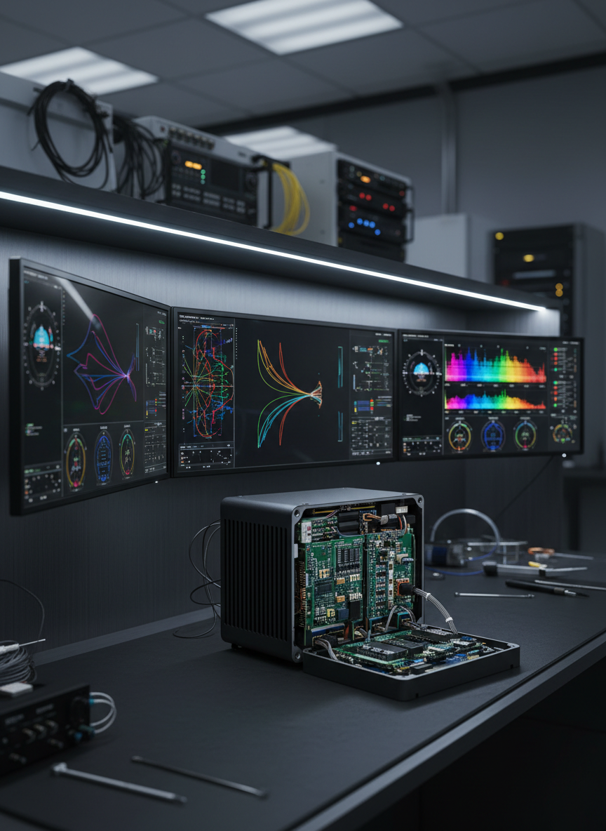
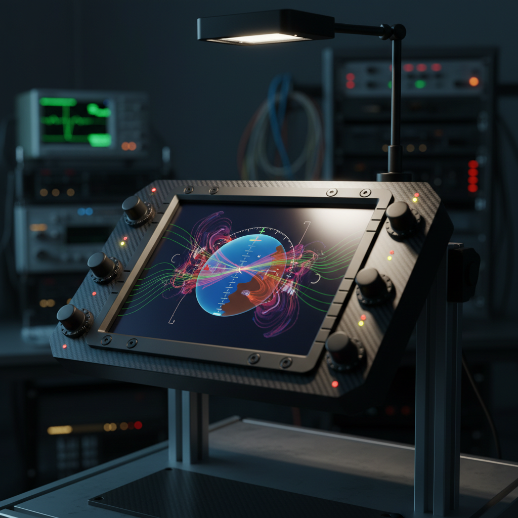
Central workspace for modeling, vibration characterization, and health monitoring algorithm validation across rotorcraft platforms.

A sleek avionics lab workbench featuring a compact rotorcraft flight computer module at the center, its matte black aluminum housing exposed to reveal meticulously arranged circuit boards, connectors, and shielded cables. Surrounding it are multiple ultra-wide avionics displays mounted on a dark, brushed-metal panel, each showing crisp, colorful synthetic flight data, vibration spectra, and sensor fusion overlays without any readable text. Cool, diffused overhead LED lighting casts precise reflections on the hardware edges, creating a clean, high-tech atmosphere. Shot at eye level with a slight three-quarter angle, the composition balances the central module against softly blurred background equipment racks, conveying a focused, professional, internal development environment in photographic realism.
A high-detail photographic scene of a rotorcraft drivetrain section mounted on a rigid test stand, its metallic gearbox housing and rotor mast instrumented with dense arrays of accelerometers and strain sensors, each connected by thin, labeled cables running to a nearby avionics rack. The background features tall, dark equipment cabinets with subtle indicator lights and a wall-mounted display showing blurred real-time vibration analysis plots. Neutral, diffused industrial lighting from overhead fixtures creates gentle reflections on machined steel surfaces and coaxial connectors. Captured from a low, three-quarter angle, the composition emphasizes the mechanical mass in the foreground with the avionics rack in sharp focus behind, conveying the integration of physical rotor systems and advanced monitoring electronics in a controlled, professional test environment.

Rotor Dynamics Models & Scope

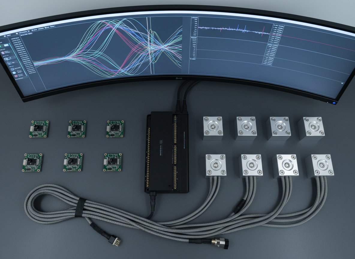
Core models define rigid and flexible rotor modes, linearized aeroelastic coupling, and steady-state operating envelopes. Assumptions, boundary conditions, and identification methods are documented per test article with references to Campbell diagrams, mode shapes, and frequency response datasets.
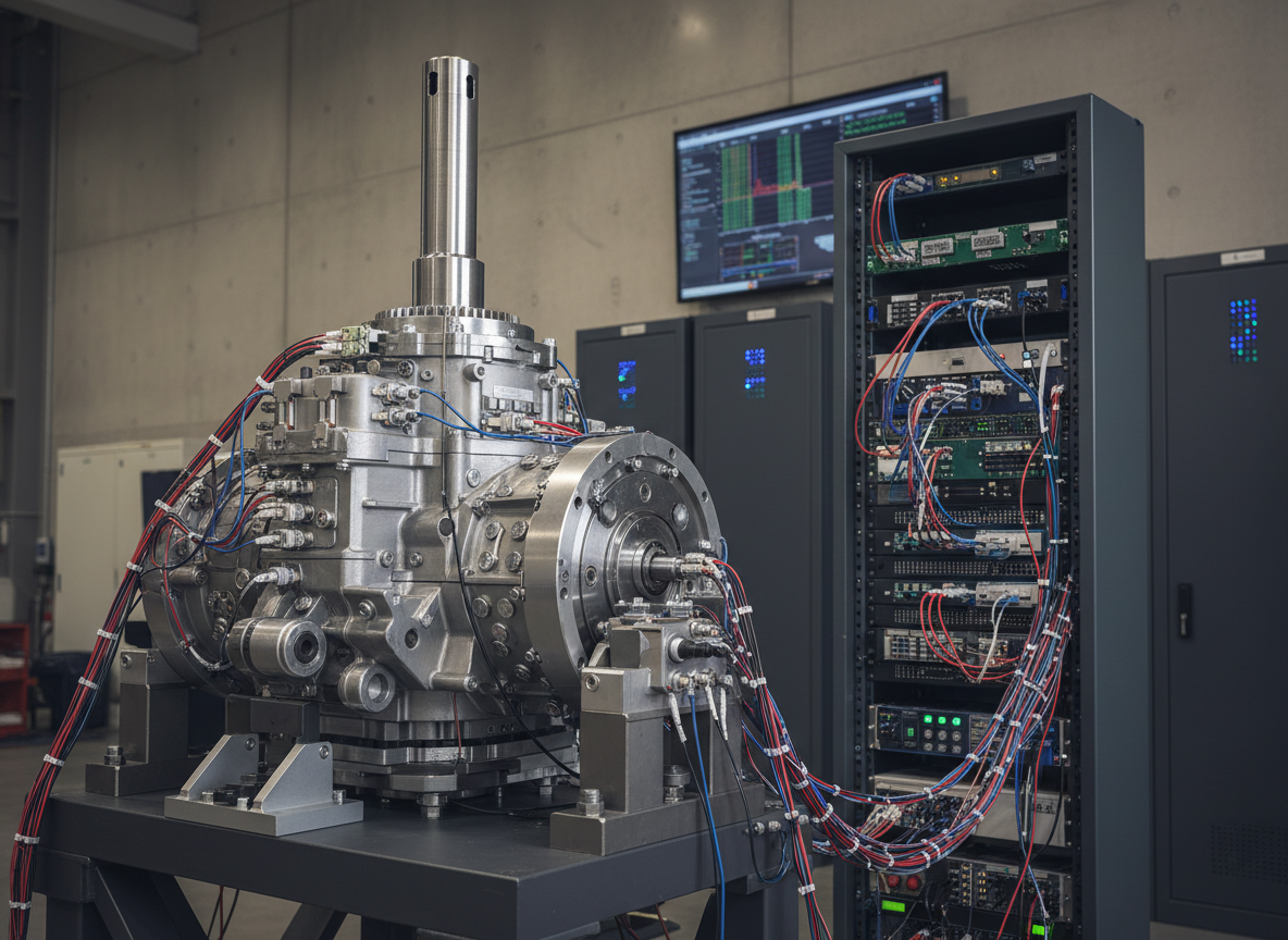
Experiments

Chronological logs of rotor tests, analysis notes, and retrospectives.